Autodesk Fusion add-in
Generate editable bearing models and shaft or housing fit sketches from a few dimensions, right inside your Fusion projects. The download includes the Windows add-in, full user guide, and source code.
- Version
- 1.0.2
- Platform
- Autodesk Fusion / Windows
- Download
- ZIP / 80 KB
- License
- MIT license
Portfolio notes
Why I made it
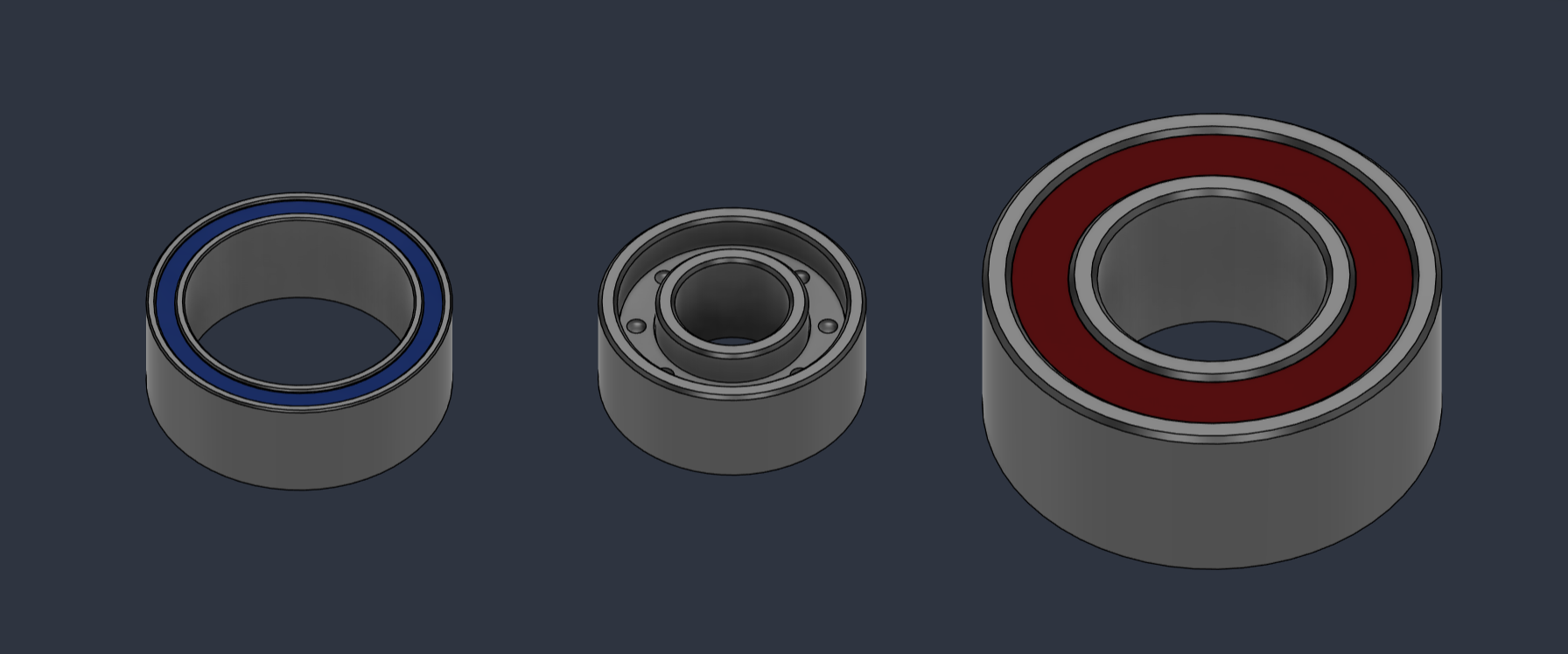
I use bearings in a lot of my projects. I wanted something better than cylinders standing in for the real parts, and a way to stop guessing at shaft and housing clearances. So I made a Fusion add-in that lets me enter a few dimensions and generate a bearing right where I need it.
Bearing Generator creates editable, single-row deep-groove radial ball bearings with separate rings, open, shielded, or sealed styles, and optional fit sketches for the parts around them.
Tool guide
Installation and usage
Install in Fusion
You need Autodesk Fusion on Windows, the Design workspace, and Capture Design History enabled. The add-in uses Fusion's bundled Python, installed steel and rubber materials, and local data. No separate Python installation or packages are needed. A minimum supported Fusion build has not been established.
- Download and extract the ZIP to a folder you plan to keep. Inside is a
BearingGeneratorfolder. Keep all of its files and subfolders together. - In Fusion, open Utilities > Add-Ins > Scripts and Add-Ins, then choose the Add-Ins tab. You can also press S and search for Scripts and Add-Ins.
- Use + / Add and select the inner
BearingGeneratorfolder containingBearingGenerator.pyandBearingGenerator.manifest. Select the folder itself, rather than the ZIP or its parent folder. - Select BearingGenerator and click Run. Enable Run on Startup if you want it available whenever Fusion opens; this is off by default.
- In Design > Solid, find Create > Create Bearing and Modify > Edit Bearing. Both commands are also available through S search.
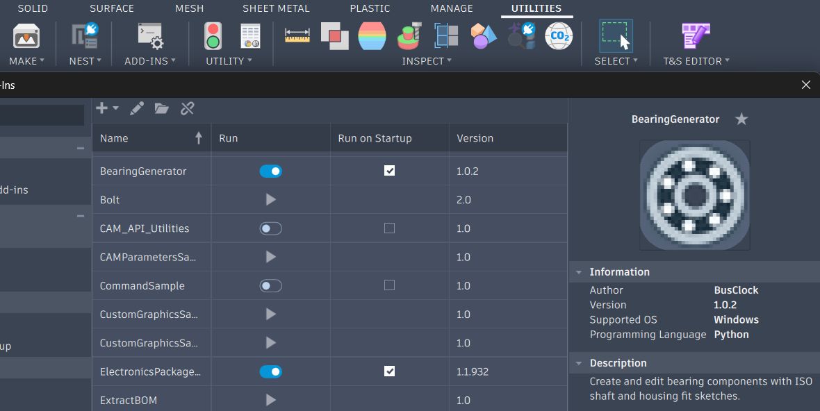
Find the commands
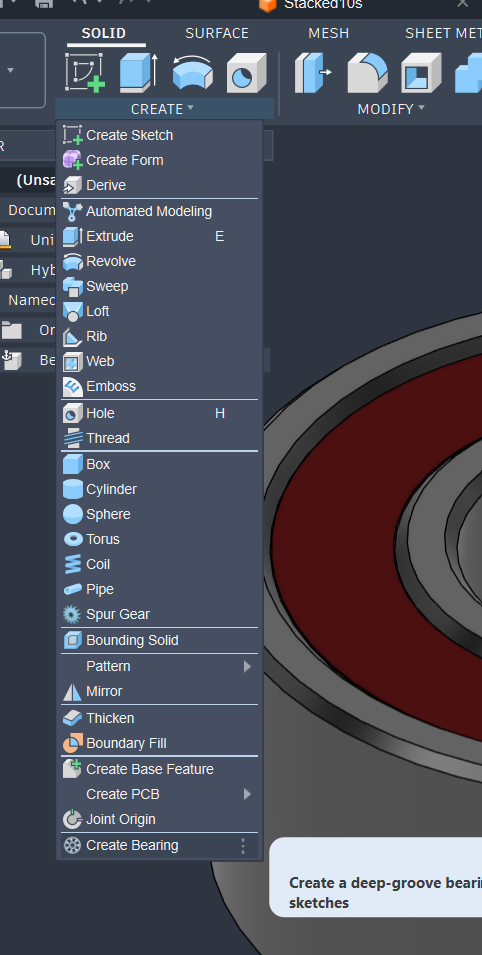
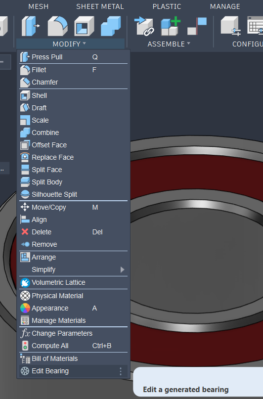
Create your first bearing
- Open a design with history enabled. For this example, set its units to millimeters and activate the component that should contain the bearing.
- Run Create Bearing. Set bore diameter d = 3 mm, outside diameter D = 7 mm, and width B = 3 mm.
- Choose shielded with red shields. Leave the geometry settings on Auto.
- Enable Preview, inspect the model, then click Create Bearing. Cancel discards the preview.
- Expand the new component in the Browser. Use Inspect > Measure to check the 3 mm bore, 7 mm outside diameter, and 3 mm width.
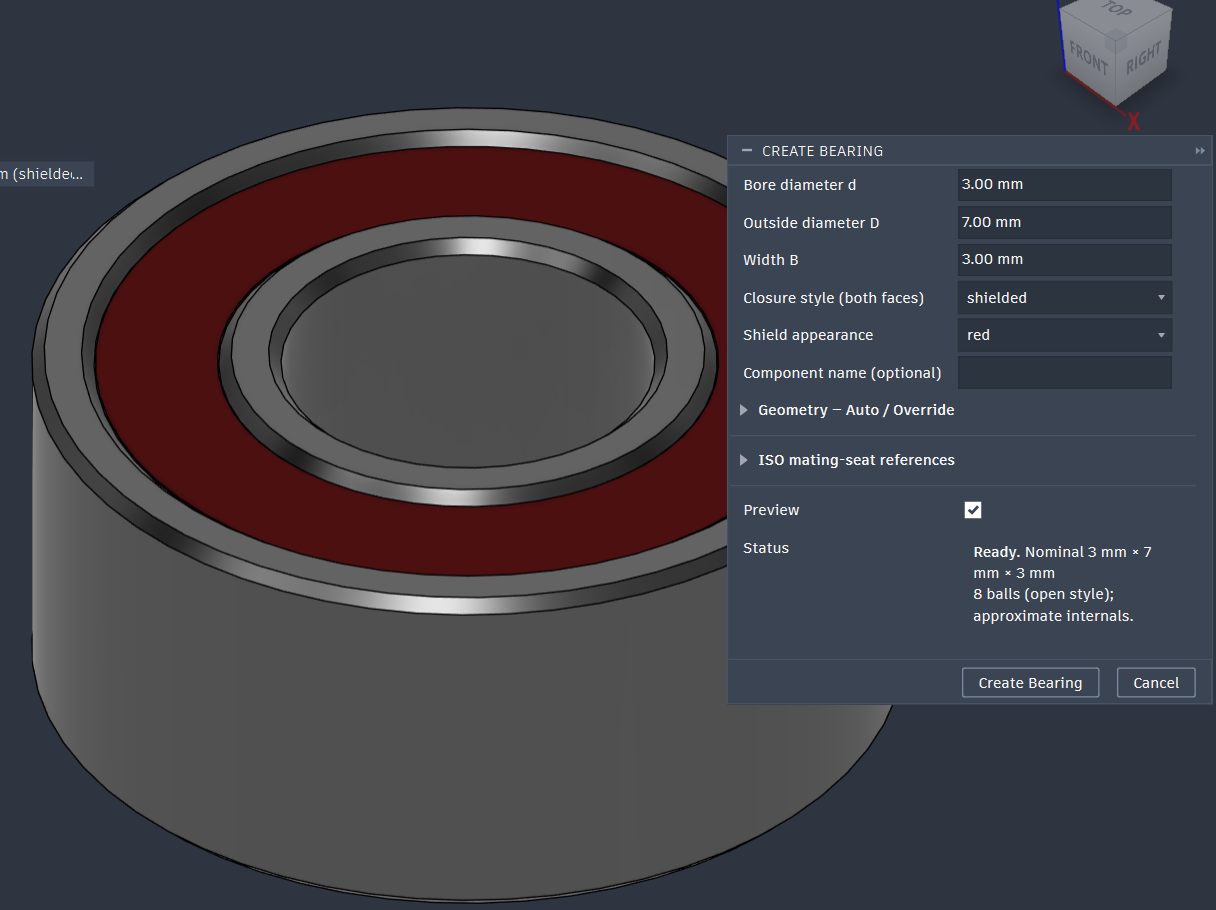
Bearings start at the active component's origin, along its local Z axis, centered on their width. Position the whole component with Move/Copy > Components or a joint so its fit sketches travel with it. Move a bearing aside before creating another at the same origin.
Choose the style
- Open: separate balls, visible raceways, and a simplified cage.
- Shielded: steel shields in gray, red, or blue.
- Sealed: rubber seals in black, red, or blue.
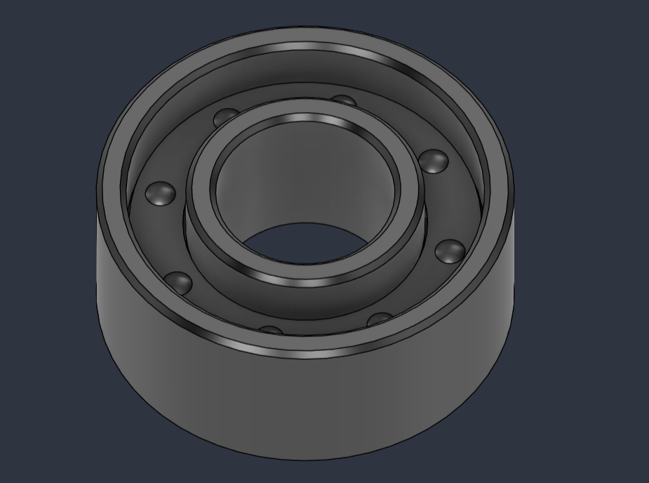
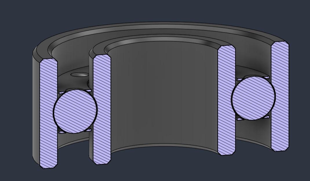
Shield and seal colors are remembered separately. Covered styles omit hidden balls and cage bodies. Under Geometry / Auto / Override, you can adjust details such as ring widths, ball count, and chamfers individually while leaving the rest automatic.
Inputs accept Fusion expressions and explicit units, including 3 mm, 0.125 in, or shaftDiameter + 0.1 mm when that parameter already exists. Each bearing remembers its own settings.
Edit an existing bearing
- Make sure the add-in is running, then open Modify > Edit Bearing.
- Select a generated bearing's component in the Browser, or one of its solid bodies in the model. You can also select the component before starting the command.
- Change its dimensions, style, color, geometry overrides, or fit selections. For red steel shields, choose shielded, then set Shield appearance > red.
- Check Preview, then click Update Bearing. Choose Cancelto discard the changes.
Here, the existing open bearing starts at 3 × 7 × 3 mm. Its outside diameter is changed to 20 mm while the bore and width stay at 3 mm. Preview shows the changed model before Update Bearing applies the edit.
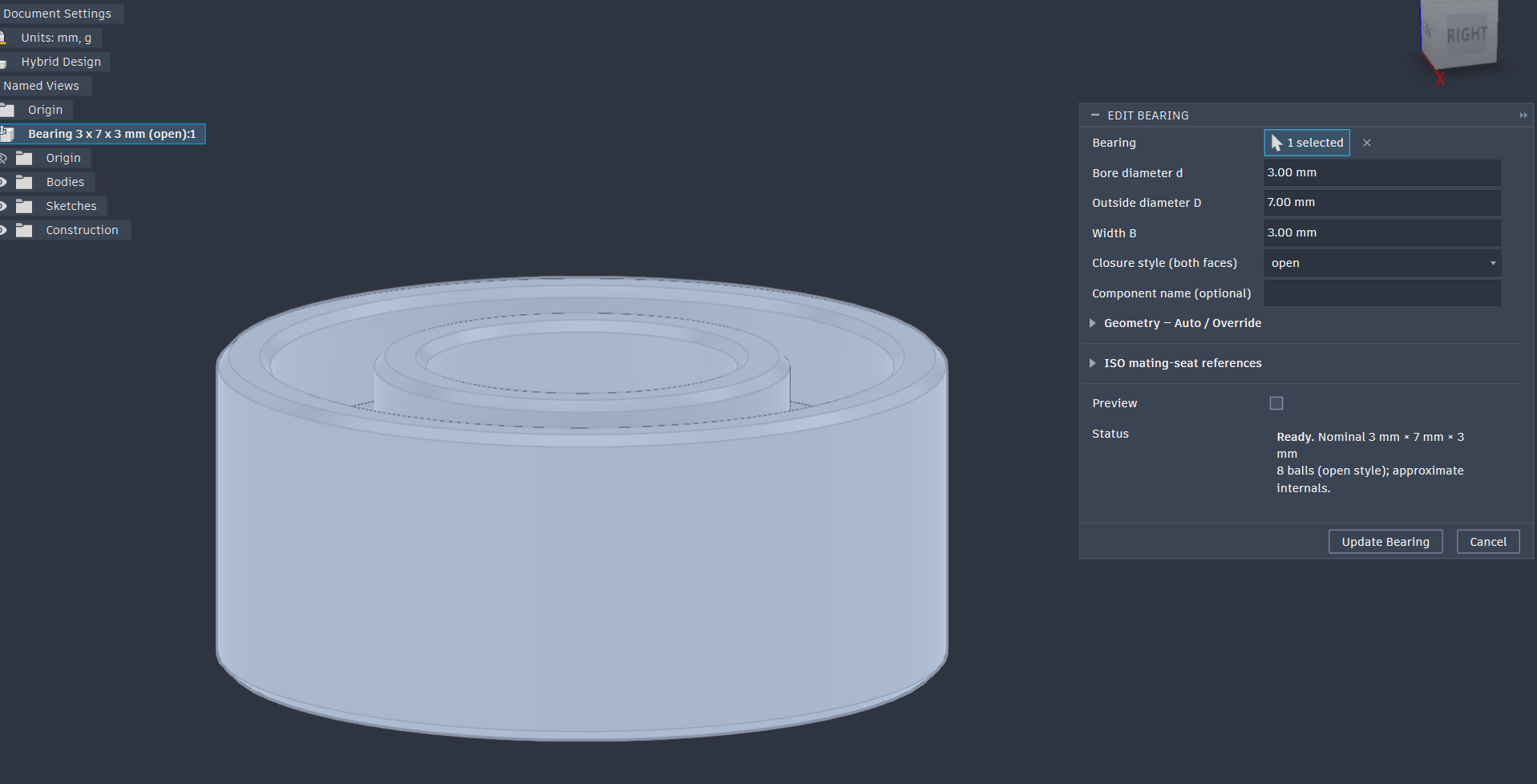
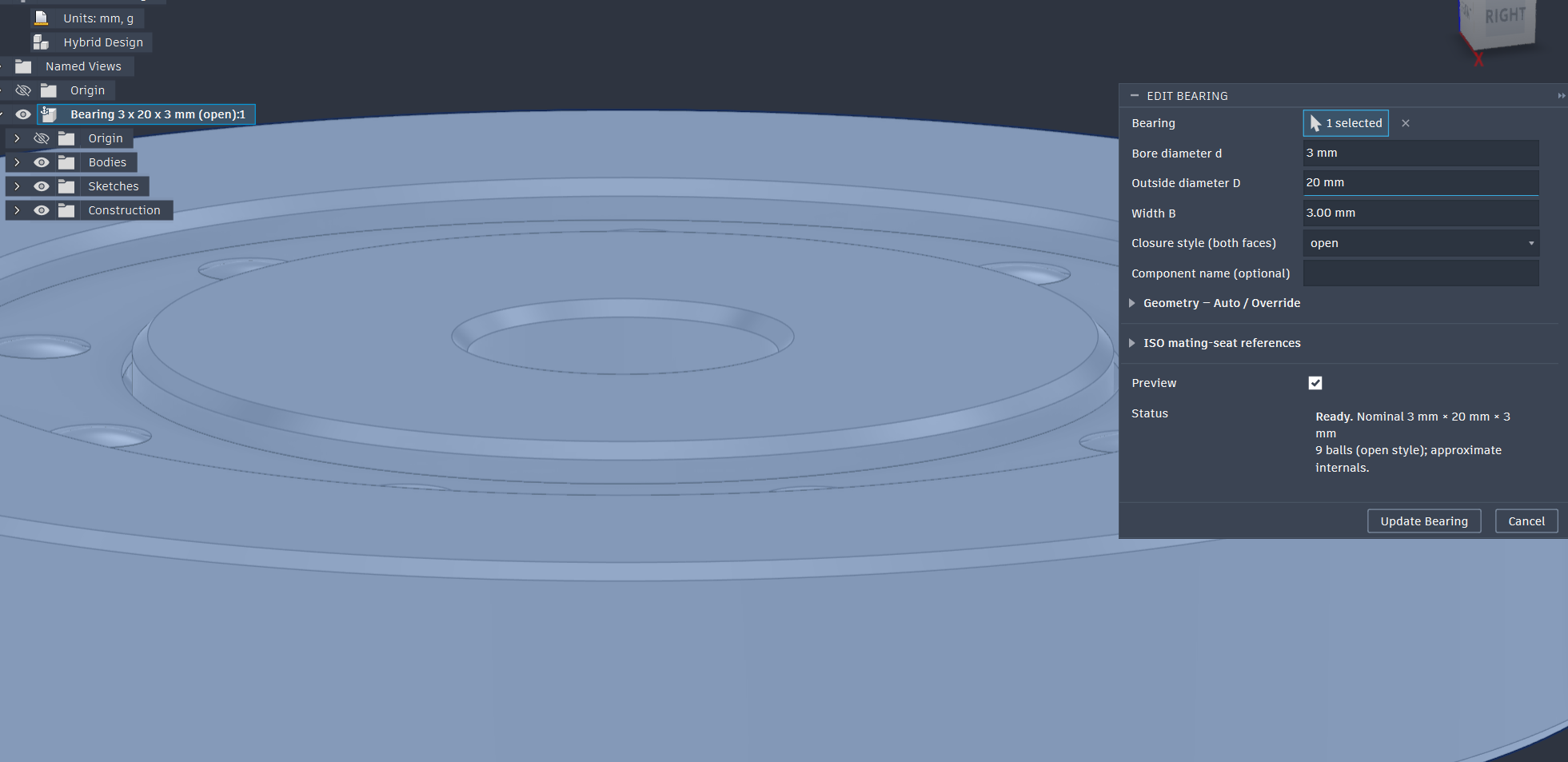
Editing retains the component and its position, along with existing fit sketches. Keep generated features, sketches, and parameters intact for later edits. Ordinary component copies can share their settings; use Create Bearing again for an independently adjustable bearing.
Build a housing or shaft from a fit sketch
The bearing stays at its nominal dimensions. Optional ISO mating-seat references give the surrounding shaft or housing its own cutting diameter, with lower and upper limits and a modeled target: midpoint, lower, or upper.
Expand ISO mating-seat references, below the geometry controls, and enable Generate ISO fit sketches. Select the shaft or housing classes you need and choose a modeled target for each one.
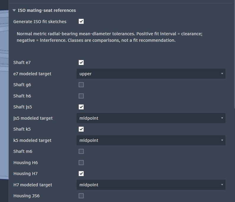
- Shaft classes: e7, g6, h6, js5, k5, m6; nominal diameters 0.6 to 500 mm.
- Housing classes: H6, H7, JS6, JS7, K6, M6, N7, P7; nominal diameters 2.5 to 500 mm.
The initial comparisons are shaft e7/js5/k5 and housing H7/JS7/P7. The report assumes Normal metric radial-bearing mean-diameter tolerances, including when your document displays inches.
A linked housing cut
- Create the 3 × 7 × 3 mm bearing with ISO fit sketches enabled and housing H7 / midpoint selected. Position it first.
- In the Browser, expand the bearing's Sketchesand reveal Housing H7 - Midpoint. These sketches start hidden on the bearing's local XY midplane.
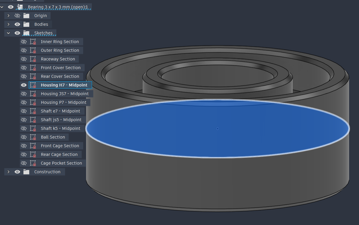
Reveal Housing H7 - Midpoint in the Browser to find the housing cutting profile.Open full size - Create a separate housing component and its blank. Start a housing sketch on a plane parallel to the bearing's fit sketch.
- Press P for Project, enable Projection Link, and select the source sketch's normal cutting circle. The other circles mark construction limits and should not be used as cutting profiles.
- Finish the sketch and Extrude > Cut its projected profile through the housing. Select only the housing as the cut participant. Choose the pocket depth or cut extent for your design.
- Hide the source sketch and measure the bore. In the included table's Ø7 H7 example, the limits are 7.000 to 7.015 mm, with a midpoint cutting diameter of 7.0075 mm.
With the projection linked, changing the bearing's outside diameter to 8 mm through Edit Bearing should update this H7 midpoint cut to 8.0075 mm. Check the resulting dimensions and timeline after updating. For a shaft, project a selected Shaft fit circle into the shaft component and use it to build the mating feature.
Fit classes are comparisons, rather than an automatic selection for your application. Choose the fit using the bearing manufacturer's guidance for your load, materials, rotation, temperature, and process. Internal geometry is approximate; the tool does not calculate bearing load ratings, life, or mounting force. The full guide and table sources are included in the download.
Updates and troubleshooting
- Commands missing? Open Scripts and Add-Ins, select BearingGenerator, and click Run. Search for Create Bearing or Edit Bearing with S.
- Installing an update? Stop the add-in, replace its whole installed folder, then fully close and reopen Fusion. This reloads all modules together. Test existing saved designs on a copy.
- No preview or action available? Read the dialog's Status message, enable design history, check that D is greater than d, and reset conflicting geometry overrides to Auto.
- Missing materials? Make steel and rubber/nitrile materials available in Fusion's Physical Material library. Matching currently uses English material names.
- Fit outside the supported size range? Create a new bearing with Generate ISO fit sketches off. Existing linked fit references cannot be resized beyond their table coverage.
- Housing did not follow an edit? Check Projection Link, the selected source circle, and timeline errors. A copied or unlinked circle will not follow later changes.
To remove the add-in, stop it, turn off Run on Startup, remove its registration if available, then delete the extracted folder you installed. Generated components remain in your designs.
The ZIP includes a longer README, changelog, and a Fusion verification checklist. Its offline checks are separate from testing inside Fusion; a complete recorded Fusion acceptance run is still pending.
Download integrity (SHA-256)
53e04683529a16efa72ac8a38d5e7fcd45251282b4579328de96ab5f9dcb31b0